Networking Overview
This section covers network configuration and setup.
Network Architecture
Tenant Network Configuration
To ensure tenant-level isolation in the compute network, different mechanisms are used depending on the underlying fabric. The configuration ensures multi-tenancy, security, and seamless integration between different network types while maintaining high performance and scalability.
Compute Network Isolation
Ethernet Network:
- Each tenant is assigned a unique VXLAN ID.
- VXLANs are extended across the fabric using BGP EVPN, providing L2 adjacency across L3 fabric.
- Each tenant's compute VXLAN ID is mapped to the corresponding tenant's converged VXLAN ID, ensuring seamless integration with the converged network.
InfiniBand Network:
- Each tenant is assigned a unique Partition Key (PKEY) to enforce network isolation.
- The tenant's PKEY is mapped to a corresponding tenant-specific converged VLAN ID, enabling interoperability between InfiniBand and Ethernet segments.
Converged Network & Isolation
The Converged Network integrates multiple traffic types, including:
- Storage Traffic: Facilitates high-performance access to storage backends such as VAST, DDN, Weka, or any other storage solution.
- In-band Management: Used for managing compute and storage resources within the infrastructure.
- External Connectivity: Enables communication with external networks and cloud providers.
For Converged Network Isolation:
- Similar to compute network isolation, per-tenant VXLANs are leveraged.
- BGP EVPN is used to propagate VXLAN mappings across the network, ensuring secure tenant-specific isolation across the entire converged network.
This approach provides multi-tenancy, security, and seamless integration between different network types while maintaining high performance and scalability.
Refer to the figure below for a detailed illustration of the tenant network configuration and isolation mechanisms.
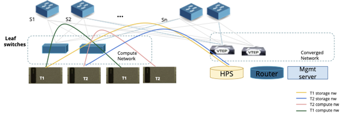
Figure 5: Fabric Level isolation for Tenants
Tenant Network Isolation Configuration Flow - Ethernet
The following example illustrates how network provisioning occurs in a Single Scalable Unit (SU) topology consisting of Leaf Switches and Compute Nodes.
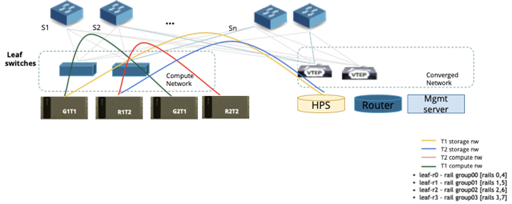
Figure 6: Fabric Level isolation for Tenants
Step 1: Underlay Network Configuration
NCP Admin triggers underlay configuration:
- This action sets up the BGP EVPN control plane across the network fabric, enabling dynamic route advertisement and tenant network isolation.
- Leaf switches are configured with BGP sessions to exchange VXLAN-based overlay routes.
Step 2: Tenant Creation (see Figure 6)
NCP Admin creates two tenants: T1 and T2. Virtual Routing and Forwarding (VRF) instances are assigned to each tenant:
- Tenant T1:
- Compute Traffic → VRF Green
- Storage Traffic → VRF Yellow
- Tenant T2:
- Compute Traffic → VRF Red
- Storage Traffic → VRF Blue
No actual configuration is applied to the switches yet. These VRFs are placeholders until workloads are allocated.
Step 3: Compute Allocation for Tenant T1
Tenant T1 requests two compute nodes. Bridge allocates Compute Nodes G1T1 and G2T1. Network setup for T1:
- Rail group switch ports (used for compute-to-network connectivity) on all leaf switches are mapped to VRF Green.
- In-band management ports on leaf switches are mapped to VRF Yellow.
Route exchange configuration:
- Routes between VRF Yellow and Default Storage VRF are exchanged, enabling storage access.
- Routes between VRF Yellow and External Network VRF are exchanged, allowing external connectivity.
Public IP addresses for G1T1 and G2T1 are assigned, along with access credentials provided to Tenant T1.
Step 4: Compute Allocation for Tenant T2
Tenant T2 requests two compute nodes. Bridge allocates Compute Nodes R1T2 and R2T2. Network setup for T2:
- Rail group switch ports on all four leaf switches are mapped to VRF Red.
- In-band management ports on leaf switches are mapped to VRF Blue.
Route exchange configuration:
- Routes between VRF Blue and Default Storage VRF are exchanged, enabling storage access.
- Routes between VRF Blue and External Network VRF are exchanged, allowing external connectivity.
Public IP addresses for R1T2 and R2T2 are assigned, along with access credentials provided to Tenant T2.
Tenants may also want to create multiple VPCs, subnets and security groups and assign various resources to specific VPCs. This would enable them to define network segmentation within their allocated resources. The network isolation for every VPC would be done in the similar mechanism as explained above.
Tenant Network Isolation Configuration Flow - InfiniBand
For managing the InfiniBand network fabric, the network is configured using the Unified Fabric Manager (UFM). Bridge is tightly integrated with UFM, enabling automated network discovery and tenant-based network isolation.
Network Discovery & Tenant Configuration
InfiniBand Fabric Discovery: During the network discovery process, the UFM controller within Bridge automatically discovers the entire InfiniBand fabric through UFM. This process identifies all switches, compute nodes, and links, ensuring visibility into the topology.
Per-Tenant PKEY Creation: When a new tenant is created in Bridge GPU CMS, UFM dynamically provisions a unique Partition Key (PKEY) for that tenant. PKEYs act as isolated virtual networks, ensuring that traffic is restricted to members within the same tenant.
Compute Allocation & Network Mapping
Network Interface Mapping: When a compute instance (bare metal or virtual machine) is allocated to a tenant, the InfiniBand controller in Bridge assigns the compute node's network interface GUIDs (Globally Unique Identifiers) to the corresponding tenant's PKEY. This ensures that the allocated compute resources can communicate securely within the tenant's isolated InfiniBand network.
By leveraging UFM integration, Bridge provides a fully automated, tenant-aware InfiniBand network configuration, ensuring seamless connectivity, isolation, and efficient resource utilization across the fabric.
Underlay Creation
After a successful topology discovery, the Super Admin must create the underlay network. This step configures IP addresses, BGP, and other required network parameters across the fabric.
Underlay creation is only required for the discovery path. If infrastructure was imported via CSV, this step is not needed.
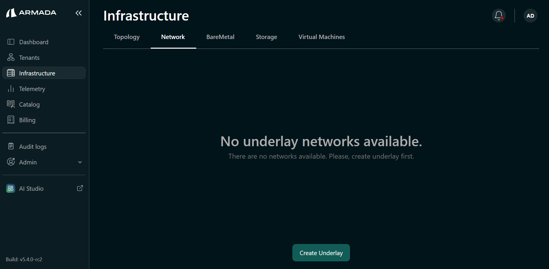
Create the Underlay
- Navigate to Infrastructure in the sidebar → click the Network tab.
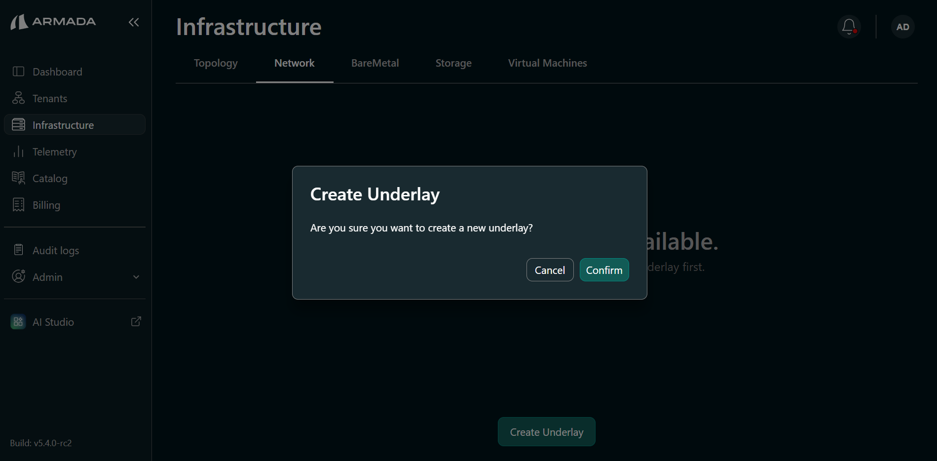
- Click the Create underlay button.
- Click Confirm to begin underlay network creation.
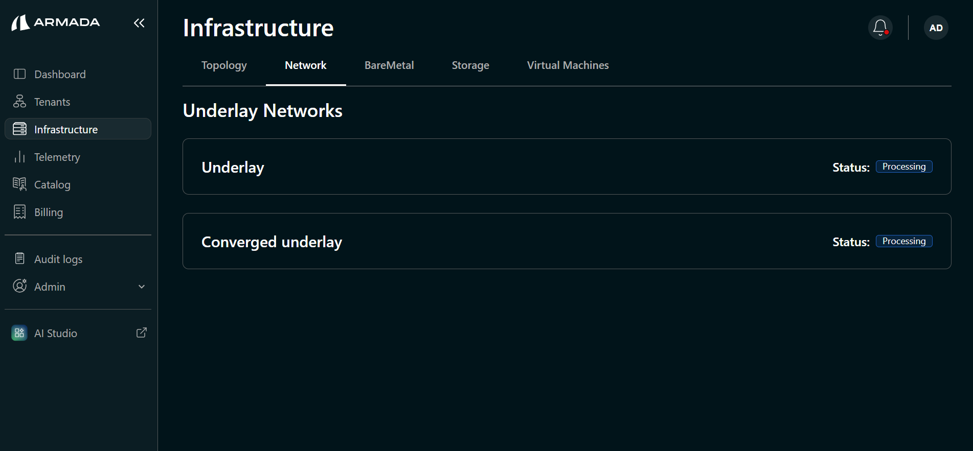
Monitor Underlay Creation
Underlay creation may take a few minutes. Monitor the compute and converged underlay status from the Network view.
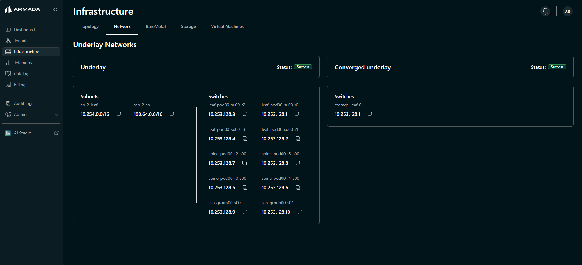
The Compute underlay is displayed under the Underlay section.
Once both underlays are created successfully, switch subnets and configured loopback addresses are shown.
Verify Underlay Configuration
Run the following kubectl commands on the amcop-0 node to verify:
kubectl get underlaynetworks -A

Verify the status of both Custom Resources (CRs):
kubectl get underlaynetworks converged-underlay -oyaml
kubectl get underlaynetworks underlay -oyaml